wp_header-bg_circuit-board_1920x1080
White Paper | WP-2002

Applying Encoders

Executive Summary

Encoders provide velocity, acceleration, direction, and position feedback to motion systems. Two basic types of feedback are absolute and incremental. Absolute encoders report unique position information at all locations and are unaffected by power loss. Incremental encoders also deliver position information, but count from a reference, which may require that a system be reset to a known start position after a loss of power.

There are several variables to consider when choosing an encoder. The most common are:

  • Style of encoder. What kind of encoder does the application call for? A shaft model, thru-bore, or blind hollow bore?
  • Resolution. For incremental encoders, resolution is defined as cycles per revolution (CPR). For absolute encoders, resolution is the number of bits that define the position count for an absolute encoder turn; e.g., 12 bits or 212 is a resolution of 4096. Single-turn resolution refers to number of counts for positions in one 360-degree turn; multi-turn resolution is the total number of full revolutions possible (turns of 360 degrees) that may be measured before resetting to zero.
  • Output type. Encoders offer a variety of different output types. Choosing the correct one means considering the number of output channels and the receiving device. See the white paper Selecting Digital Encoder Outputs for more information.
  • Frequency response, or the maximum frequency of the output signal in Hertz.
  • Accuracy, which is the difference between the theoretical position of one increment or bit edge and the actual position of the edge.
  • Electrical connections.
  • Environmental conditions. Specifically, encoders must withstand a range of conditions such as moisture and dust that can seep into internal optics and electronics. Sealed encoders are available to address this. For more information on sealing options on encoders, see technical bulletin TB-106: Sealing Options for EPC Encoders.

There are also encoders available that address other environmental conditions, including exposure to corrosive and caustic chemicals and ambient temperatures that reach up to 120° C. For more information, refer to the white paper, Encoders in Inhospitable Environments.

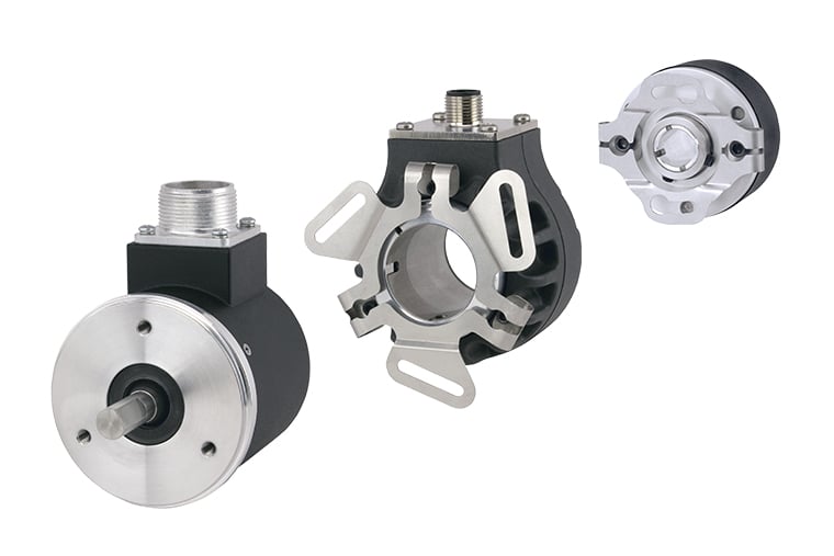
wp2002_encoder-examples_760x507

Examples of typical encoders. From left to right: Size 25 shaft encoder, 58 mm thru-bore encoder, 1.5 inch blind hollow-bore encoder.

Common Interfacing Issues

Designers must identify an encoder resolution that reflects the system’s true needs. Resolution that is too high can increase costs and raise frequencies above the encoder or receiver’s capabilities. Also, higher resolution doesn’t necessarily translate into higher system accuracy. On the other hand, resolution that’s too low may limit the system’s ability to control speed or position accurately. Additionally, incremental encoders with quadrature phasing not only provide directional information, but can increase resolution up to four times when combined with a compatible receiving device.

A system’s receiving device (controller) generally dictates encoder output. Thus, designers should first determine the controller’s input requirements, and then select a compatible encoder output driver. For more information, refer to our white paper Selecting Digital Encoder Outputs.

Three basic types of controllers exist:

  • Drivers that supply current to external devices (sourcing)
  • Drivers that provide a current path to the circuit ground or common (sink)
  • Drivers that do both (line drivers)

Many controllers accept differential line-driver signals, canceling common-mode noise while accommodating long encoder cable runs.

Mounting and Installation

Mounting and installation depend on the style of the encoder. Thru-bore and blind hollow-bore encoders slide over and clamp onto a precision shaft, attaching directly to the motor frame through a flexible mount. A proper fit between the bore and shaft, as well as a good flex mount design, help retain accuracy and encoder bearing life.

Shaft encoders, on the other hand, usually mount to a fixed surface and couple to a driven shaft. Alignment between the shafts and the coupling’s design and quality also impact accuracy and encoder bearing life.


An EPC Model 25T thru-bore encoder, being installed on a motor

Optimizing Encoder Signals

To reduce the potential for electrical noise degrading an encoder’s signal, follow these key steps:

  • Connect the encoder cable shield to ground on the receiving device.
  • Properly ground the motor or machine to which the encoder is mounted.
  • Ensure that the encoder cable is of high quality and low capacitance with foil and braided shields. Also, avoid routing encoder cable near electrically noisy power cables or equipment.
  • For more information on encoder signals, see the white paper Noise and Signal Distortion Considerations for Encoders in Motion Control Applications.

Conclusion

When considering how to apply an encoder for motion feedback in an industrial application, there are several basic factors to consider. There are a variety of resources available to aide in research for a solution. However, there are motion control experts well-versed in encoders and their options who can guide you to the right motion feedback solution for your application.

If you have a question about which encoder is right for your application, contact EPC. You’ll talk to real engineers and encoder experts who can answer your questions about encoders and motion feedback, and you’ll get answers that make sense for your application.

EPC’s corporate headquarters is in the United States. We offer expedite options on most models, even same-day options. With our industry best three year warranty, if something does go wrong, we’ve got you covered.

Contact EPC today to find the right motion feedback device for your application.

downloadDownload the PDF

Applying Encoders