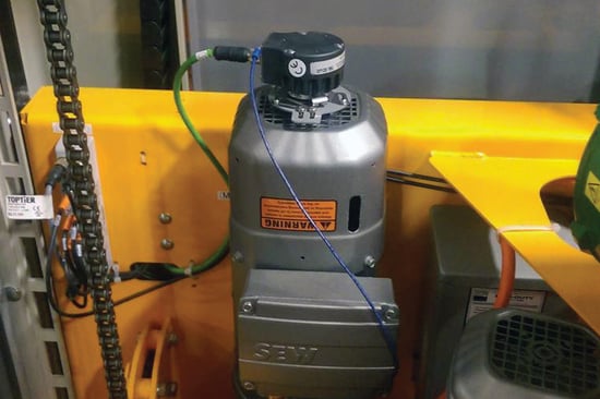
Motor encoders are rotary encoders adapted to provide information about an electric motor shaft's speed and/or position. Like rotary encoders in general, motor encoders are most commonly magnetic or optical and produce signals that are either incremental or absolute. Mechanical packages for motor encoders can be shaft, thru-bore or blind hollow bore, or modular solutions. Shafted motor encoders use a flexible shaft coupling to connect the encoder shaft to the motor shaft. Thru-bore or blind hollow bore housings connect directly to the motor shaft via a shaft collar. The encoder housing can then be mounted directly to the motor housing, or with a flexible tether arm, or a mounting bracket.
The Model 25H blind hollow bore encoder shown with a three-point (SE) flex mount
Several factors affect the choice of a motor encoder for a given application, including (1) the type of motor involved, (2) the mounting configuration required, and (3) the type of information required by the control system.
Motor encoders, like all rotary encoders, indicate shaft movement in one of two ways: incremental or absolute. Choosing one of these options is typically the first step toward choosing the right motor encoder.
Incremental motor encoders are generally used to provide information about a motor shaft’s speed and direction by means of two clock channels, labeled A and B. The pulse rate indicates speed while the leading or lagging of channel A or B indicates direction. In the case of servo motors, an incremental encoder can also provide commutation channels, commonly known as U, V, W channels. The resolution of these U, V, W channels directly correlates to the number of magnetic poles on the motor. The commutation channels are used to properly align the windings and the magnets of the rotor and the stator and are how the control system knows when to energize certain windings to achieve optimal power and torque.
Absolute motor encoders indicate the shaft’s angular position as well as the direction and speed of its movement. In the case of servo motors, the use of an absolute encoder eliminates the need for the U, V, W channels. The same absolute data used for position, direction, and speed is also used for proper commutation alignment. The two basic types of absolute motor encoders are single-turn and multi-turn.
Single-turn encoders only allow for control systems to know the angular position of the motor shaft within a single revolution. The motor shaft can of course rotate more than a single revolution, but the number of complete shaft rotations is unknown when using a single-turn encoder.
Multi-turn encoders provide data that includes the number of complete shaft revolutions. This allows the control system to know how many complete revolutions the motor shaft has turned and the angular position of the shaft within its current revolution.
When speed control is an encoder’s only function, absolute feedback may be an unnecessary expense due to the higher cost of the encoder and requisite control system. In the case of speed control, incremental feedback meets the needs of the application and is the most cost-effective solution.
When the motor shaft’s actual position at any given time is important to the application, absolute encoders are crucial. For applications that require retained position information over multiple rotations due to functional requirements or after power loss, a multi-turn absolute encoder is needed.
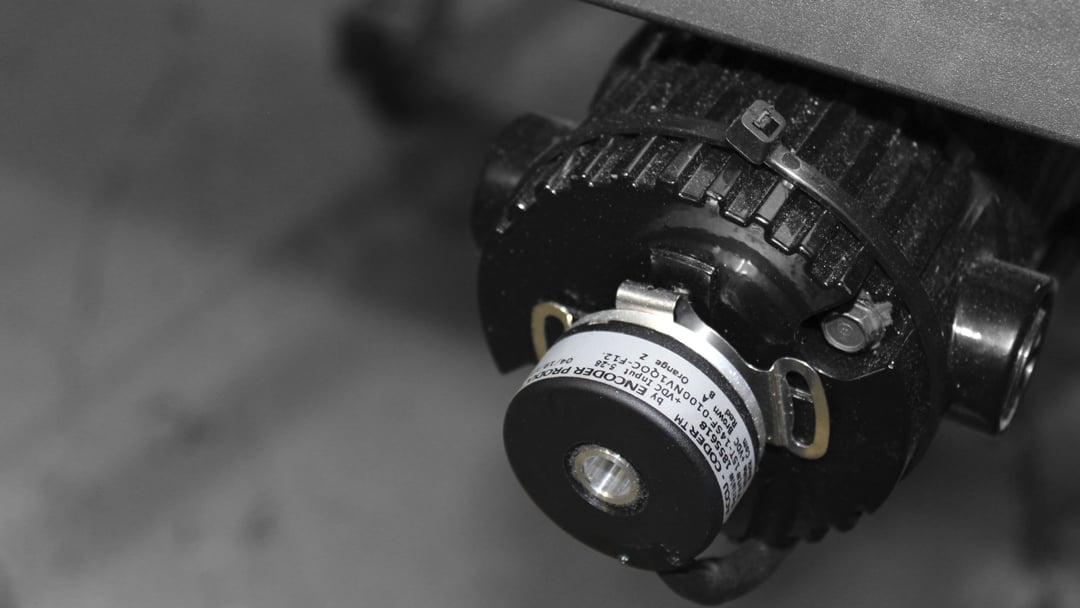
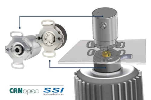
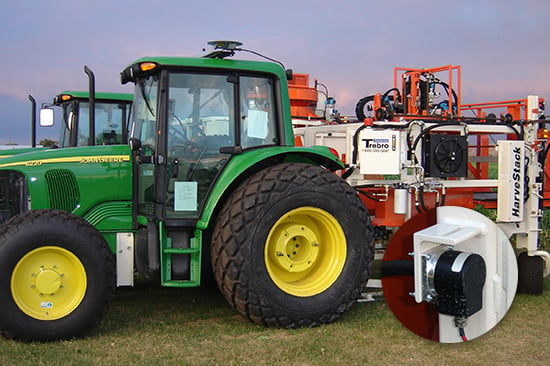
Stacking an absolute encoder with an incremental encoder on a motor shaft provides redundant feedback for applications that can't lose position information, like autonomous vehicles
Multi-turn thru-bore or blind hollow bore Model A36R Absolute Encoder
Each type of electric motor places its own set of demands on the accompanying motor encoder. In most cases, this reflects each motor’s typical range of uses.
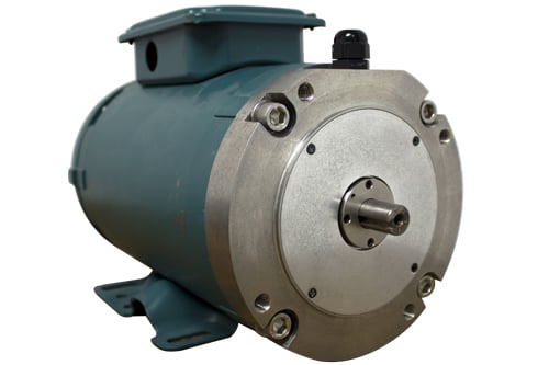
AC induction motors are cost-effective, sturdy, and durable. These qualities make them especially common in a wide range of automated machine control systems. Motor encoders give AC motors a greater degree of speed control than they otherwise would have. Because AC motors are used so widely, most applications put a premium on shock and vibration resistance. Encoders with industrial connector options like a conduit box, latching, or mil-spec are often preferred.
The exact speed of DC motors can be especially difficult to control without closed-loop feedback. Isolated from the rest of a system, a wound-wire shaft rotating within a stator’s magnetic field can be measured with some precision; in real-world applications, motor encoders are often the only way to inform the system about a DC motor’s exact speed.
Permanent magnet motors, or servo motors, tend to be used in situations where precision is more important than power. Servo motor encoders follow suit and are often designed as high-resolution absolute encoders for use in closed loop systems. Incremental encoder feedback, when coupled with the appropriate control system, can be a lower cost feedback alternative for servo motors.
Stepper motors provide position information by virtue of their design, making them popular, cost-effective components in open loop systems. This feature also prevents them from offering precise speed control, especially when loads change frequently and suddenly. Stepper motor encoders provide closed loop feedback for more precise control, and are often incremental to enhance the position control inherent in stepper motor design. Many stepper motors are compact in size and are suitable for modular encoders that do not use bearings.
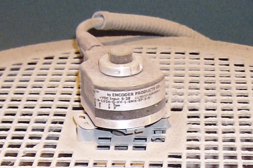
A Model 260 thru-bore encoder with a dust-tight IP64 seal
How an encoder will mount to the motor is the final major consideration when selecting a motor encoder. The most common designs are as follows.
Traditionally, motor feedback is achieved with a shafted encoder coupled directly to the motor’s shaft. This gives shafted motor encoders a degree of electrical and mechanical isolation that other designs do not. Coupling a shafted encoder to a motor requires a long enough motor shaft for secure mounting, however. A poorly joined coupling can negatively impact a motor’s performance by altering the shaft’s angle. In many designs, a bell housing or standoff is used between the motor and encoder. These considerations typically add cost to shafted motor encoders.
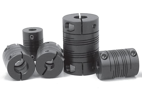
Flexible shaft couplings for securely joining shafts
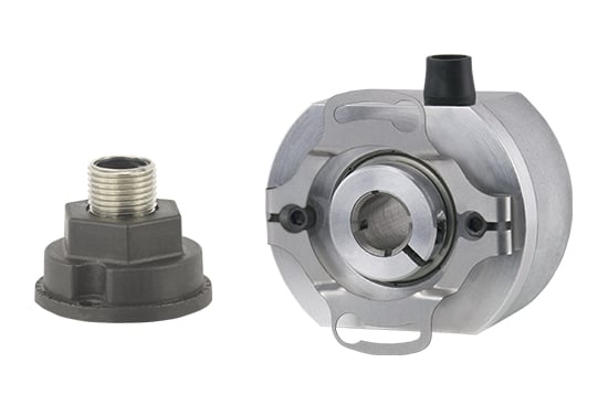
Thru-bore and blind hollow bore/hollow shaft encoders are easier to install than shafted packages: they mount directly to the motor shaft via a pass-through shaft collar and usually use a flexible steel tether arm to attach to the motor housing. Some thru-bore housings attach via a motor-compatible housing, such as a C-face design. This approach does not require a separate coupling or subsequent shaft alignment. Thru-bore motor encoders do not inherently provide electrical isolation unless equipped with non-conducting bore inserts and mounting bushings. Most thru-bore and blind hollow bore/hollow shaft motor encoders usually have lighter duty bearings and housing structure and are typically lower cost than shafted models as a result.
A stainless steel thru-bore encoder mounted on a NEMA C-face motor
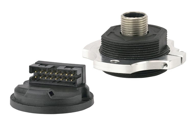
Modular encoders feature an encoder disk that is mounted directly to the shaft, without a bearing assembly. A separate sensor module is supported by a light duty housing. Benefits of this design are compact size and lower cost due to the reduced mechanical components. Additionally, the lack of bearings enables the encoder to operate at very high speeds – 30,000 RPM or higher – and without drag or starting torque. Modular encoders can be susceptible to shock and vibration, due to the absence of bearings or a stabilizing housing structure. Another drawback is that most designs require additional installation effort to ensure the disk and sensor are properly aligned and gapped.
Bearingless encoder modules
Like modular encoders but larger in scale, ring-mount motor encoders involve a sensor assembly mounted to the motor’s housing, and a magnetic wheel mounted to the motor’s shaft. The result is typically more resistant to shock, vibration, and contaminants than an optical encoder, but the magnetic wheel can place extra mechanical demands on the motor itself. Therefore, ring-mount encoders are especially useful in heavy-duty applications involving more powerful motors with more robust frames. Ring-mount encoders use relatively coarse resolution when compared to optical encoders, and are suitable only for speed and direction feedback.
We're here to help. Our engineers and encoder experts will respond quickly to your toughest, most technical encoder questions.
Expedite options are available on many models. Contact us for details.