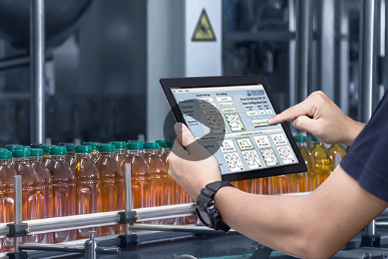
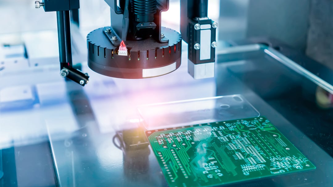
Increasingly, manufacturers rely on a growing array of machine vision systems to improve production throughput, product quality, and product traceability. These systems are integrated into both stationary manufacturing equipment and mobile platforms such as AGVs or AMRs. Common applications include positioning, identification, verification, measurement, and flaw detection. Some examples are object detection, qualitative inspection, gauging (fill-level, length, etc.), counting, identification (1D and 2D), and guidance, such as robotic pick and place. Rotary encoders frequently play a critical role in these systems.
Machine vision systems typically consist of a digital camera, a light source, and a computer processor that analyzes the captured images. To obtain an image of sufficient quality, the distance from object to lens, lighting intensity, and exposure duration all need to be synchronized. Two synchronization methods are used, either time-based, when object speed is constant, or distance-based, when object speed can vary. While a variety of sensor types can be used for time-based synchronization, incremental encoder feedback is almost always required for distance-based timing.
A key function of encoder feedback within vision systems is to trigger image capture at the appropriate time. As an example, in an inspection application for parts transported on a conveyor, the edge of an approaching object is detected by a photoelectric sensor. The system counts encoder pulses from the point of detection, with each pulse representing an interval of distance traveled. The light and camera are triggered when the desired count is achieved, indicating the part is in the correct position for image capture. The encoder pulses are also used to time the camera exposure. For multi-camera applications, encoder input can be used to trigger each camera at specific intervals.
A surface-mounted encoder with measuring wheel provides conveyor motion feedback to a pick and place robot.
Two methods of image capture are used in factory automation: area scan and line scan. Area scan cameras capture an entire 2D image in a single frame. The size of an area scan image is determined by the number of pixels on the sensor. Area scan cameras often rely on time-based synchronization.
Line scan cameras capture a single line of pixels, with each exposure occurring as the object moves past the camera. The successive pixel lines are then digitally assembled to render the complete image. With line scan cameras, it's important that the camera's frame rate is synchronized with the object's travel. Otherwise, images can be distorted by compression or extension. This is where encoders play an important role in the vision system.
Since the line scan camera creates an image of a moving object one row of pixels at a time, the interval between exposures must be timed precisely to avoid distortion from too many or too few pixel lines. The key encoder attribute that creates successful imaging is encoder resolution, stated as Cycles Per Revolution or CPR. Factors dictating encoder resolution are image size, image resolution, frame rate, and transport speed. The image acquisition card or camera software may include scaling capabilities that allow the user to correlate a line of pixels with a certain number of encoder pulses.
For encoder transport applications, the speed of the conveyor belt must be measured accurately to ensure the image is free of distortion. An encoder with measuring wheel, such as the Model TR1 Tru-Trac, is a common means of obtaining accurate belt speed feedback. The EPC Model TR1 is an easy to use, linear measurement solution that is readily integrated with vision sensors for conveyor speed feedback.
Typically, the pixel dimension for each image line dictates encoder resolution. For example, if an inspection process requires a minimum of 5 pixels per mm to identify a defect, the pixel dimension is 0.2 mm/scan. Each encoder pulse will trigger a scan, so encoder resolution should be 5 pulses per mm of belt travel. With a measuring wheel circumference of 200 mm, the desired TR1 Tru-Trac encoder resolution would be 1000 CPR.
Encoders can be surface-mounted (center) or shaft-mounted (left) to provide conveyor feedback.
Some installations can benefit from a programmable encoder, such as Model 58TP or Model 25SP that offer resolutions from 1 – 65,536 CPR. For example, to compensate for changes to other system components (conveyor, lighting, image field, etc.) or inspection attributes, the encoder resolution may need to be tuned to an optimal CPR to eliminate image defects. For an OEM of inspection equipment, a programmable encoder can facilitate installation of devices on a wide range of customer applications and operating environments.
As always, it’s best to consult the specifications of the vision system devices to ensure compatibility with the encoder output circuit type, voltage, current, and frequency. To assist with determining encoder frequency, use our CPR, RPM & Frequency Calculator.
Programmable encoders are often ideal for conveyor feedback where cameras are used.
A properly configured rotary encoder is a key component in many high-performance machine vision systems. Both end user and OEM system designers benefit from encoders that have configuration options to meet a wide range of application requirements, as well as attributes such as accuracy and reliability. Contact the EPC Sales Team or an EPC Distributor Partner for assistance in selecting and specifying encoders for your next machine vision system.
We're here to help. Our engineers and encoder experts will respond quickly to your toughest, most technical encoder questions.
Expedite options are available on many models. Contact us for details.