There are four essential criteria to consider when selecting the optimal encoder for each unique application.
When you are specifying an encoder for an inkjet system, there are several variables to think about. Let's start with the basics: there are four essential criteria to consider when selecting the optimal encoder solution for each unique application:
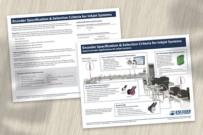
Some of those variables are predetermined by encoder interface requirements. See our publication, Encoder Specification & Selection Criteria for Inkjet Systems, for more information.
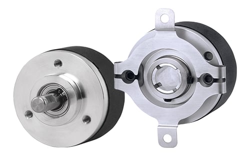
When choosing your encoder, it is critical to consider how and where the encoder will be applied in your application. The first question to answer is whether you need a thru-bore or a shaft encoder.
Thru-bore encoders mount directly to the shaft via a collar, and are anchored by a flexible anti-rotation mount. Their bearings are designed to carry the encoder only. See all incremental thru-bore encoders.
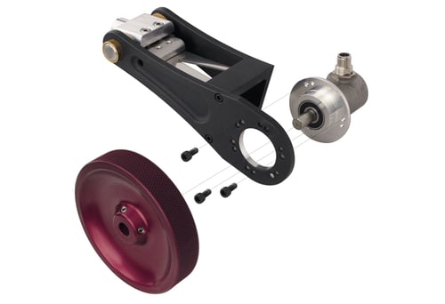
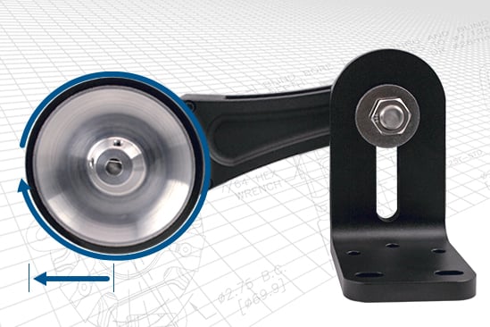
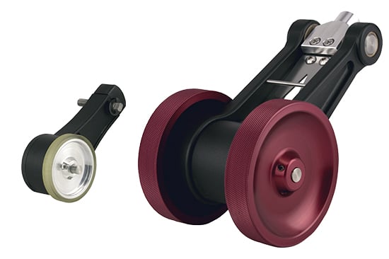
Shaft encoders can carry heavier loads and can be used with a measuring wheel. For more information on choosing the right measure wheel, see technical bulletin TB-108: Encoders with Measuring Wheels. See all incremental shaft encoders.
To define your mechanical requirements, determine the following:
Model 15S shaft encoder (left) and Model 15T thru-bore encoder (right) shown with a two-point flex mount.
Often, industrial ink jet systems are used to mark products that are in motion on a conveyor or other transport system. The encoder resolution, defined as Cycles Per Revolution (CPR), usually provides the printer a measurement in pulses per inch (or millimeter) of linear travel of the product to be marked. To determine encoder pulses per inch/mm, it’s necessary to calculate the exact distance the product travels with each rotation of the encoder shaft. Measuring wheels are often used for this purpose.
For example, an encoder with a resolution of 4000 CPR and a 200 mm wheel riding on the conveyor surface yields 20 pulses per mm of linear travel. Generally, the encoder resolution is specified to yield a pulse per inch/mm rate that meets printer requirements. If the encoder is applied to a headroll shaft, drive belt, or a servo motor, the ratio between encoder rotation and linear travel is a more complex calculation. CPR specification is commonly provided by someone familiar with the system design and sensing/control requirements.
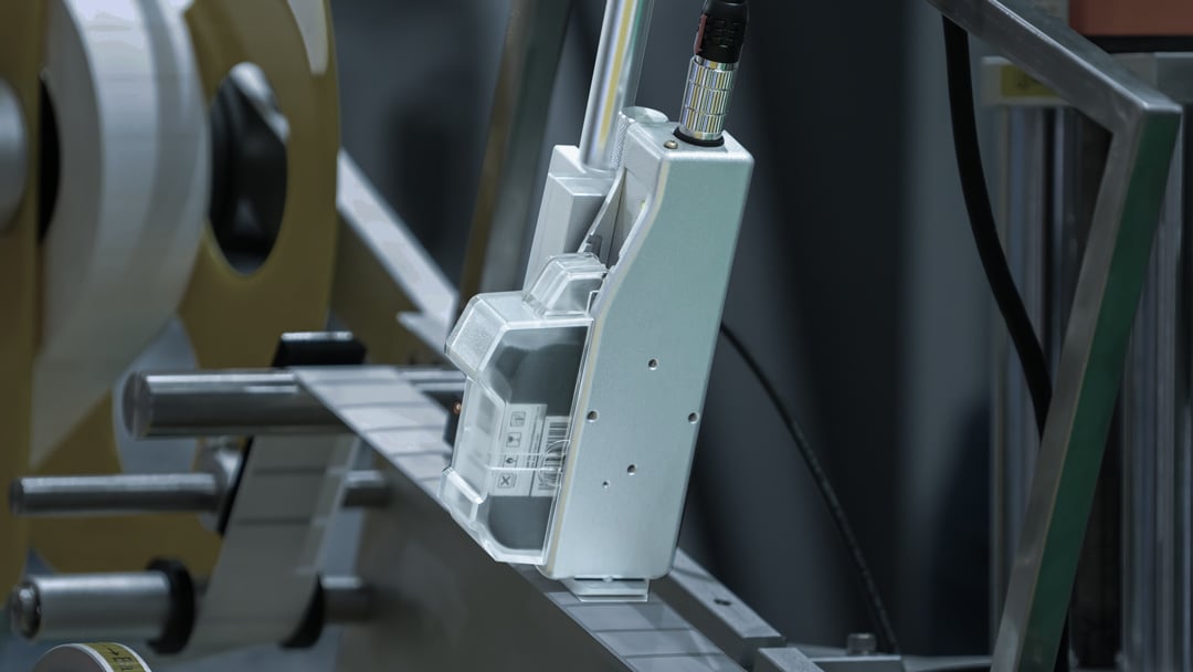
Use EPC's linear measurement calculator to calculate CPR/PPR for measuring wheel applications.
Depending on what kind of environment an encoder could be exposed to in your application, you could need protection from anything from dust to liquids. To learn more about sealing options on encoders, see Technical Bulletin TB-106: Sealing Options for EPC Encoders.
It's important to consider the distance between the encoder and the receiving device (controller, PLC, counter, etc.) when specifying your encoder. For distances that are more than 10 feet, select body-mounted connectors. These allow for ease of installation and make after-market service simpler. Many EPC encoders offer integrated M12 cordsets, and flying leads are available on all models. For cable lengths exceeding 30 feet, consult EPC Technical Sales Engineers.
Of course, encoder interface requirements are also a vital point to consider. For more information on interface requirements, and more technical and in-depth information on specifying the right encoder for your inkjet system, see our publication, Encoder Specification & Selection Criteria for Inkjet Systems (PDF), for more information, or give us a call. When you contact EPC, you talk to engineers and motion control experts who can answer your toughest encoder questions. Contact EPC today.
Download the PDF Encoder Specification & Selection Criteria for Inkjet Systems
We're here to help. Our engineers and encoder experts will respond quickly to your toughest, most technical encoder questions.
Expedite options are available on many models. Contact us for details.