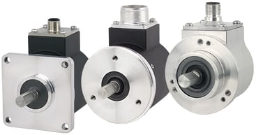
Size 25 shaft encoders (2.5” diameter), along with their 58 mm diameter European equivalents, are among the most popular encoders in the world. As a result, nearly every encoder manufacturer in the world makes them. This technical bulletin identifies and compares important features of Size 25 shaft encoders, including typical designs, and the Encoder Products Company (EPC) Accu-Coder® Models 725N, 725I and the programmable Accu-CoderPro® Model 25SP.
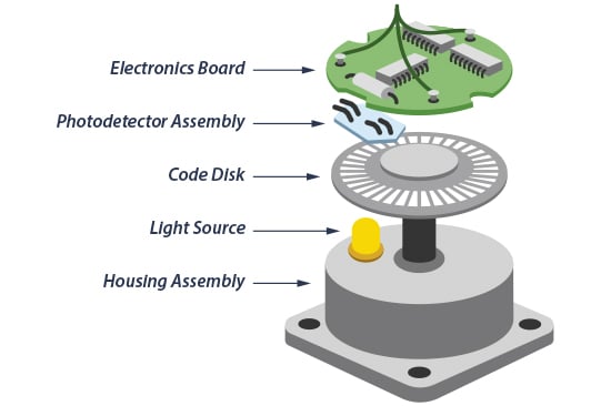
The typical construction for a Size 25 optical shaft encoder is shown at right (Figure 1). In a rotary encoder, the disk is fastened to a rotating hub while the sensor is mounted to a fixed printed circuit board (PCB). Light passing through the disk pattern as it rotates past the sensor produces the signals that become the square wave output.
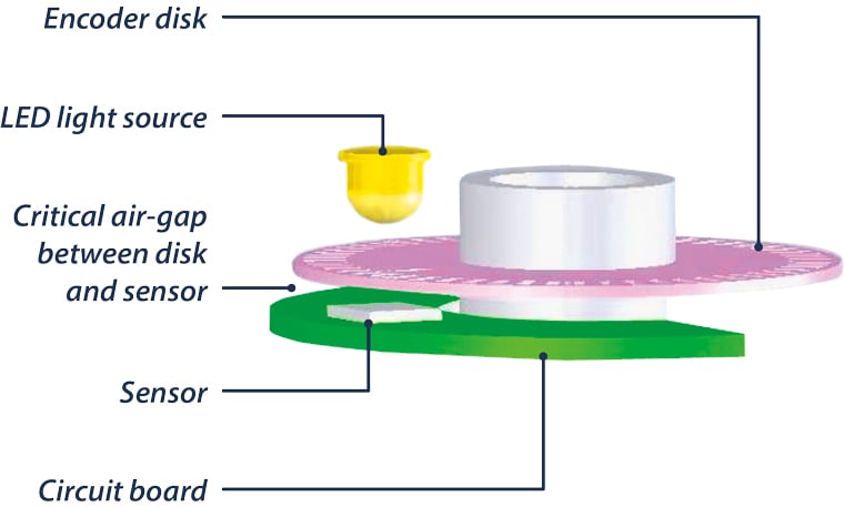
During design and manufacture, the air gap between the disk and sensor (Figure 2) is adjusted to calibrate the encoder in order to produce the optimal square wave. The air gap for typical Size 25 encoders can be as little as 0.002”. For resolutions over 1200 CPR, the air gap can be even narrower.
This narrow air gap presents a potential problem: radial or axial loading can move the shaft in such a way that the attached disk can contact the sensor or other portion of the PCB. The resulting condition, known as disk-crash, usually renders the encoder inoperable or, at best, unreliable due to damage to the disk or sensor.
Figure 1.
In extreme situations, the properties of the disk itself can also make it prone to failure. With typical sensor technology and manufacturing methods, the disk is made as large as possible and is a relatively thin 0.030” thick. The shaft hub that attaches to the disk supports just 15% of its total surface area, making it vulnerable to the slightest impact. These factors combine to increase the likelihood of disc fracture.
When specifying a Size 25 shaft encoder, it’s important to evaluate the potential hazards to the encoder. Heavy shaft loads, shock, vibration, dust, and moisture can greatly reduce the operating life of ill-equipped encoders. Typical Size 25 shaft encoder designs are not adequate to provide long lasting, reliable feedback in such conditions. For demanding industrial applications, preference should be given to encoders that feature:
Manufacturers often do not publish all of these specifications in their product literature. This presents a challenge when specifying an encoder. For example, short of physically examining a disassembled sample of the encoder, it may be difficult to determine the disk diameter or sensor/disk air gap. Most manufacturers, however, do publish specifications for shock, vibration, shaft loading and environmental sealing. This information offers some measure of guidance for encoder specification. For industrial rotary shaft encoder applications, preferred ratings are:
Figure 2.
EPC’s Model 725N was engineered to address the weak points that can affect a Size 25 shaft encoder’s performance. This design was then used to develop the next generation Model 25SP, offering programmable features. With the Model 25SP, users may program the waveform, output type, and resolution to configure it to almost any application.
Two important considerations were part of the design process to develop the new, improved Size 25 shaft encoder. First, cost-prohibitive solutions were avoided. Second, the design was kept within the common Size 25 shaft encoder dimensions. The encoder would need to perform reliably in a wide range of operating conditions, including: heavy axial and radial shaft loads, shock, vibration, dust, dirt, moisture, and extreme temperatures. Also, the encoder needed to be a direct replacement for encoders already installed in the field, as well as a reliable option for OEM manufacturers that wouldn’t require them to alter existing designs. The Model 25SP meets all these objectives.
The Model 25SP incorporates the following features to improve on typical designs:
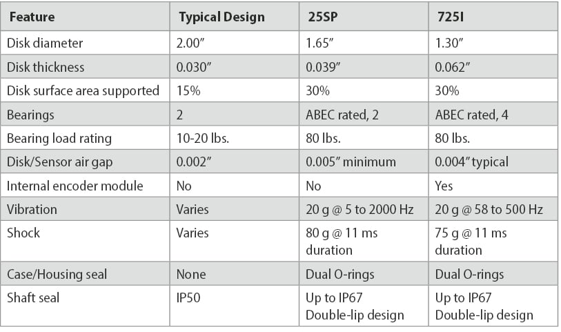
Model 25SP Accu-CoderPro® vs. typical Size 25 shaft encoder design:
The design features of the Model 25SP are also incorporated into other EPC shaft encoder models, including:
Model 725N
Size 25 (2.50") incremental encoder
Model 702
Size 20 (2.00") incremental encoder
Model 802S
Size 20 (2.00") incremental encoder with stainless steel housing
Model 758
58 mm incremental encoder
Model 858S
58 mm incremental encoder with stainless steel housing
While the design used for the Model 25SP eliminated the weaknesses inherent in typical Size 25 designs, another alternative was developed that further enhances encoder performance and reliability. The Model 725I (the "I” stands for industrial) offers an extremely robust encoder, while still remaining within the target price category.
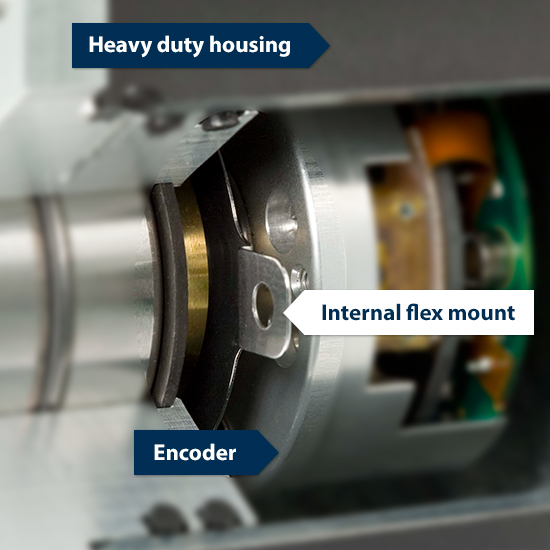
The Model 725I has two primary and distinctive features that contribute to its ability to absorb shock, vibration and shaft loading with no adverse effects on function or performance:
Model 725I cutaway.
While there are numerous choices for Size 25 shaft encoders, Encoder Products Company Model 25SP and Model 725I meet or exceed preferred specification ratings for encoders that go into the types of applications where a Size 25 Shaft Encoder is called for.
The following chart summarizes features of a typical design for Size 25 encoders, EPC’s Model 25SP, and EPC’s Model 725I:
If you have additional questions about using a measuring wheel with an encoder, or about using a Tru-Trac™ linear measurement solution, please contact EPC Customer Service at 800-366-5412 or email sales@encoder.com.
TB-118 Rev F, 03/07/2022