A
Absolute Encoder
An absolute encoder provides information in the form of unique output for every resolvable movement of motion or shaft rotation.
Accuracy
Related to the incremental encoding disk. It is the difference between the theoretical position of one increment or bit edge and the actual position of the edge.
Ambient Temperature
The average or mean temperature of the surrounding air that comes in contact with the equipment and instruments under test.
Axial Loading
The force applied to a shaft end surface directed along the axis of rotation.
Axial Load (maximum)
Maximum axial load is the maximum force that may be applied to the shaft without reducing the rated operating life or causing deviation from the rated performance.
B
Bi-Directional
Bi-directional refers to an encoder output code format from which direction of travel can be determined.
Binary
A number expressed in the base-2 numeral system, using only two numerals, 0 and 1.
Bit
Short for "binary digit." It is the smallest unit of digital data and has a single binary value of either 0 or 1.
Least Significant Bit: The bit in a binary number that is of the lowest numerical value, 20.
Most Significant Bit: The bit in a binary number that is of the highest numerical value, 2n, where n is the resolution in bits of the binary number.
C
CANopen
A high-level serial communication protocol and device profile specification for embedded systems used in automation based on the CAN protocol. CANopen standard consists of an addressing scheme, several small communication protocols, and an application layer defined by a device profile.
CE (European Compliance)
Sets essential electromagnetic compatibility, within the European markets, for all electrical and electronic equipment that may interfere with other equipment, or that may be interfered with other equipment.
Channel
Each channel is a unique incremental output of the encoder.
Complementary
Complementary is the term for two identical periodic signals where one signal is electrically inverted from the other. Example of single channel electrically inverted. Complementary signals are typically generated by inversion of the electrical output from a single channel.
Current Sinking Output
A logic form that requires current flow out of the input of the PLC or counter and back to the output of the encoder. The encoder sinks this current, which is sourced by the input circuitry. This is the most common output circuit configuration. It uses an NPN output transistor in the encoder.
Current Sourcing Output
A logic form that requires current flow from the output of the encoder to the input of the counter or PLC. The encoder sources the current and the input circuitry of the counter or PLC sinks this current. This output circuit is seldom used. It usually requires a PNP output transistor in the encoder.
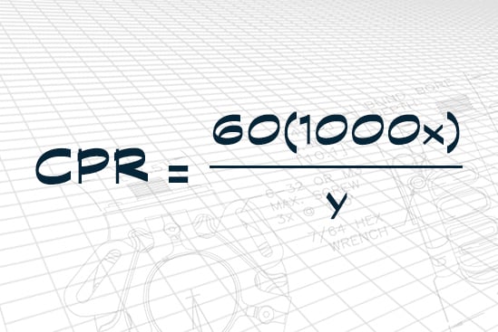
Cycles Per Revolution (CPR)
The number of increments on the disk of an incremental encoder. A one-thousand-increment encoder has a CPR of 1000.
D
Differential Line Driver
Output stage of the encoder that produces two "complementary" pulse trains per output channel. These complementary outputs can be transmitted through long cables with minimal loss of signal integrity. Electrical noise effects are reduced when the signals are compared by the "differential line receiver." Receiver input impedance should be matched to the line driver output and the transmission line for best noise immunity.
Disk
Typically made of glass, metal or plastic with precise position incremental lines. These lines are also known as increments. The number of increments determines the resolution, or CPR, of the encoder.
Dual Channel
A dual-channel encoder produces two incremental outputs. These two outputs are generally in quadrature (90° phase separation) relationship to each other. They are typically referred to as Channel A and Channel B.
Duty Cycle
The total time to complete one on/off cycle.
E
Encoder (shaft type)
An encoder is an electro-mechanical device that translates mechanical motion (such as position, velocity, acceleration, speed, or direction) into electrical signals.
Frequency Response
Frequency response for an incremental encoder is the maximum frequency of the output signal in Hertz.
G
Gray Code
A binary code used in computing in which consecutive integers are represented by binary numbers differing in only one digit. Useful for error detection.
I
Incremental Encoder
An incremental encoder is a device that provides a series of periodic signals due to mechanical motion. The number of successive cycles corresponds to the resolvable mechanical increments of motion.
Index Reference
The index is a separate output generated by a special track that produces a single cycle (or transition change) at a unique position or positions such as center, home, zero, or reset point. Sometimes referred to as a "marker pulse."
IP50
Protected against dust. Limited ingress (no harmful deposit).
IP64
Totally protected against dust. Protected against water sprayed from all directions. Limited ingress permitted.
IP65
Totally protected against dust. Protected against low pressure jets of water from all directions. Limited ingress permitted.
IP66
Totally protected against dust. Protected against strong jets of water. Limited ingress permitted.
IP67
Totally protected against dust. Protected against the effect of immersion between 15 cm and 1 m.
IP69K
Totally protected against dust. Protected from steam-jet cleaning.
L
Line Count
The number of equally spaced radial lines per 360 mechanical degrees on the incremental encoder code disk.
Line Driver
A circuit that provides error-free output pulses in electrically noisy environments or over long transmission lines when used with a line receiver.
N
Negative Going Pulse
When activated, the pulse goes low (logic 0) or in a negative direction. Do not be confused by negative going, meaning the pulse goes negative in relationship to the signal common or reference level. These statements are for positive logic only. All shaft encoders are based on positive logic.
NEMA 4
Enclosure rating intended for indoor or outdoor use primarily to provide a degree of protection against windblown dust and rain, splashing water, and hose directed water; undamaged by the formation of ice on the enclosure.
NEMA 13
Enclosure rating intended for indoor use primarily to provide a degree of protection against dust, spraying of water, oil, and noncorrosive coolants.
Noise
An undesirable electrical signal from an external source such as an AC power line, motors, generators, transformers, fluorescent lights, CRT displays, computers, radio transmitters, and others.
O
Open Collector Output
When the signal is taken directly off the collector element of the output transistor, no pull-up is used. This is the electronic equivalent of a mechanical switch closure to common. The input device of the PLC or counter is effectively placed in a series circuit that includes the output transistor and input device, which is often an optoisolator and the positive voltage supply. When the output transistor turns on, the circuit is completed and current will flow. The output signal can not be observed unless the circuit is completed externally.
P
Phase
Phase is electrical degrees of displacement between two encoder outputs, typically 90° in quadrature encoders.
Position Error
Position error is the difference between the theoretically correct shaft position and its position as indicated by the encoder cycle count.
Positive Going Pulse
In the low or logic 0 state, it is in the quiescent state. It goes high or logic 1 when activated. This is a transition in the positive going direction.
Pulses Per Revolution
Number of pulses occurring in one revolution of the encoder shaft.
Pulse Polarity
Either positive going or negative going. A pulse has two logic states: activated or inactivated. These two states are opposite. When the pulse is in its quiescent state (high or low), it is at one particular logic level (1 or 0). When the pulse hits or is in the activated state, this logic level reverses itself for the duration of the pulse.
Pulse Width
The actual real time between identical points on the leading or trailing edge of a pulse to the next successive leading or trailing pulse edge. The pulse width of the output signal of most encoders is a 50% duty cycle on the clock outputs. Some models utilize a timed or "one shot" output. This provides a constant pulse width irrespective of the pulse repetition rate or shaft speed. The factors to be considered when determining pulse width specifications are: 1) the minimum pulse width requirement of the counter or PLC, which is available in the counter or PLC specifications; 2) pulse repetition rate versus pulse width. With a constant pulse width, the individual pulses become closer together as the pulse repetition rate or shaft speed increases. At some point, the pulses will overlap and the output signal as a series of well defined pulses ceases. The pulse repetition rate varies inversely with the pulse width, and vice versa.
Pull-Up Resistor
When added inside the encoder between the positive voltage and the collector element of the output transistor, it becomes a pull-up circuit. This is also known as a pulse output.
Push-Pull Output
An output circuit that will both sink and source current.
Q
Quadrature
A dual output encoder used for bi-directional motion control. One channel leads the other by 90 electrical degrees. By monitoring the phase shift of both channel A and B, direction can be determined. Another benefit of a quadrature encoder is count multiplication. With an appropriate counter, resolution can be multiplied up to four times. For instance, by using this technique, an encoder with CPR of 1000 can provide a resolution of up to 4000 pulses per shaft revolution.
Quadrature Error
Quadrature error is the phase error when the specified phase relationship between two channels is nominally 90 electrical degrees.
R
Radial Load
The force applied at a specific point to the encoder shaft perpendicular to the axis of rotation. Note: It is important to note where the force is being applied along the shaft, due to the cantilever effect.
Radial Load (maximum)
The maximum force that may be applied perpendicularly to the shaft without reducing the rated operating life or causing deviation from the rated performance.
Resolution
The number of increments on the encoder disk. For incremental encoders, resolution is defined as cycles per revolution (CPR). For absolute encoders, resolution is the number of bits that define the position count for an absolute encoder turn; e.g., 12 bits or 212 is a resolution of 4096. Single-turn resolution refers to number of counts for positions in one 360-degree turn; multi-turn resolution is the total number of full revolutions possible (turns of 360°) that may be measured before resetting to zero.
S
Serial Synchronous Interface (SSI)
Serial interface standard for industrial applications between a master (e.g., controller) and a slave (e.g., sensor). A clock pulse train from a controller tells the device when to send out data bits; one bit of position data is transmitted to the controller per one clock pulse received by the sensor.
Shaft Run Out
Amount of shaft movement while spinning.
Single Channel
A single channel encoder produces one incremental output. They are often used for tachometry applications.
Solder Terminals
For applications that require direct solder connections to the shaft encoder.
Symmetry
Symmetry is the ratio of the ON time to the OFF time of the output signal for one channel. This ratio is optimally 50-50.
T
TIR
Total Indicator Reading
Torque (running)
Running torque is the rotary force required to keep an encoder shaft turning. It is typically expressed in ounce-inches.
Torque, Starting (breakaway)
Starting (breakaway) torque is the rotary force required to overcome static friction and cause the encoder shaft to begin rotating.
U
Unidirectional
An encoder output code format from which direction of travel cannot be determined.
W
Word Length
The total number of bits which represent the position value for an absolute encoder; e.g., 12 bits of single-turn resolution and 13 bits of multi-turn resolution would mean a total word length of 25 bits.